![]() In this article we want to introduce the IceCube Neutrino Observatory. In a first part we focus on the input of KIT and DESY for the developments of SiPM-readout scintillation detectors for an extended surface array of IceCube and IceCube-Gen2.
In this article we want to introduce the IceCube Neutrino Observatory. In a first part we focus on the input of KIT and DESY for the developments of SiPM-readout scintillation detectors for an extended surface array of IceCube and IceCube-Gen2.
IceCube is a unique detector, not only due to the discovery of very high energy cosmic neutrinos, but also as a multipurpose research facility. It also contributes to cosmic ray physics, dark matter searches and glaciology, and is therefore most suitable for multi-messenger astroparticle physics.
IceCube Neutrino Observatory
The IceCube Neutrino Observatory is located at the South Pole to observe the cosmos using optical modules deep in the ice and ice Cherenkov tanks at the surface (IceTop).
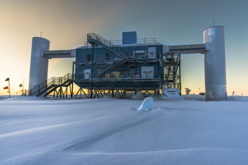
IceCube Lab at sunset
(Credit: Martin Wolf, IceCube/NSF)
With 5160 digital optical modules, deployed in a cubic kilometre of ancient ice at 1450 m to2450 m depth, this in-ice component measures Cherenkov light generated by neutrino induced particles in the TeV energy range. The optical modules are employed with a ten-inch photomultiplier and corresponding electronics. 60 optical modules form one string and in total 86 strings are deployed.
The DeepCore subdetector with denser configuration lowers the energy threshold to 10 GeV and allows the investigation of neutrino oscillations.
IceTop acts as a veto and calibration detector for IceCube and is additionally used as a cosmic ray particle detector in an energy range from 300 TeV to 1 EeV.
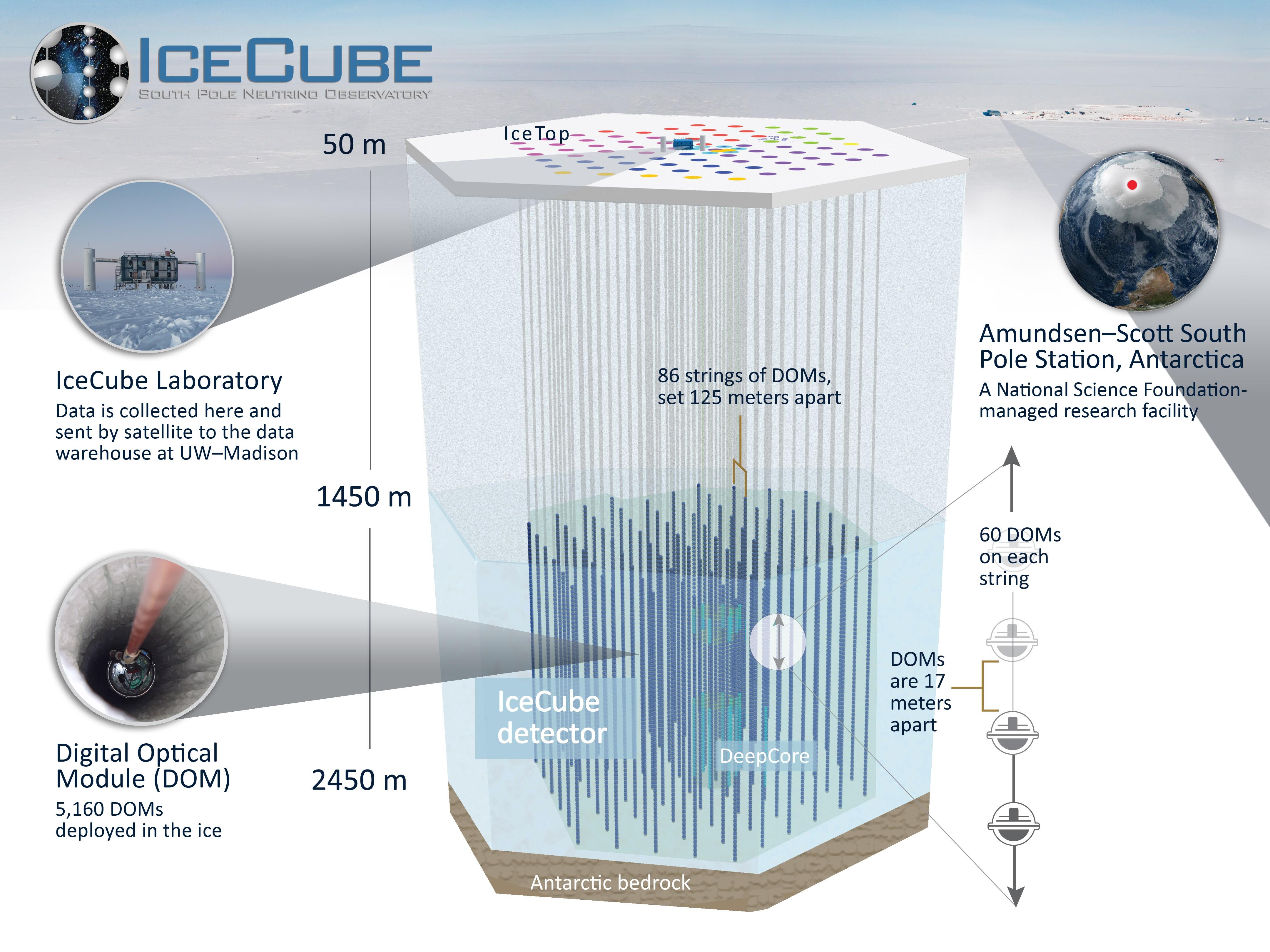
IceCube detector schematic
(Credit: IceCube Collaboration)
A collection of science highlights in the different fields can be found on: http://icecube.wisc.edu/science/highlights
Further information about the IceCube Neutrino Observatory is available at their website: http://icecube.wisc.edu/
IceCube-Gen2
Due to the excellent performance of the detector and the discovery of the astrophysical neutrinos the idea of a next-generation Neutrino Observatory was natural. The new IceCube-Gen2 collaboration is currently exploring the capabilities of such a detector.
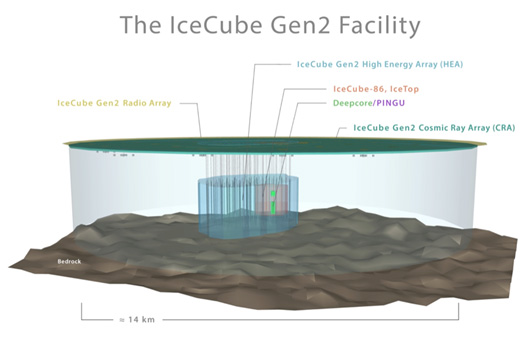
IceCube-Gen2
(Credit: IceCube collaboration)
The future IceCube detector shall deliver statistically significant samples of very high energy astrophysical neutrinos, in the PeV to EeV range, and detect hundreds of neutrinos across all flavors at energies above 100 TeV. It includes the dense array PINGU, but also a radio enhancement like ARA is considered for detecting neutrinos above EeV. In addition, the in-ice instrumentation shall be complemented by a large-area surface component for veto issues and cosmic ray measurements.
IceCube-Gen2 is presented in more detail here: http://icecube.wisc.edu/science/beyond
At the moment several R&D projects are going on and in Part I we focus on the work of KIT and DESY on a future scintillator surface array and on Part II we show the developments of optical sensors for the IceCube Upgrade.
Part I
R&D at KIT and DESY for IceScint
An array of scintillation detectors can be used to increase the veto capabilities for cosmogenic neutrinos and enables an improvement in the reconstruction of cosmic-ray induced air-showers. The Institut für Kernphysik at KIT and the astroparticle group at DESY decided to build such a scintillator array combining the existing TAXI DAQ, developed by DESY, with newly developed scintillation detectors based on the knowledge gained at KIT by building also the upgrade of the Pierre Auger Observatory, AugerPrime.
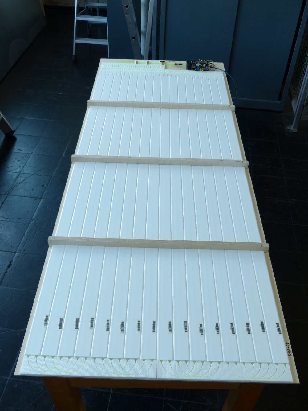
The IceScint detector is made of Fermilab scintillator bars and wavelength shifting fibres readout by state-of-art silicon photomultipliers (SiPMs).
With the single photon calibration stand at KIT (SPOCK) the most suitable SiPM for scintillator readout was specified and before installation, the SiPM characteristics of each installed SiPM were measured. The 6x6mm² Hamamatsu S13360-6025PE was found to be best suited for the specific requirements. Below the Photon Detection Efficiency and the Gain as a function of the overvoltage for one of the installed SiPMs are shown:
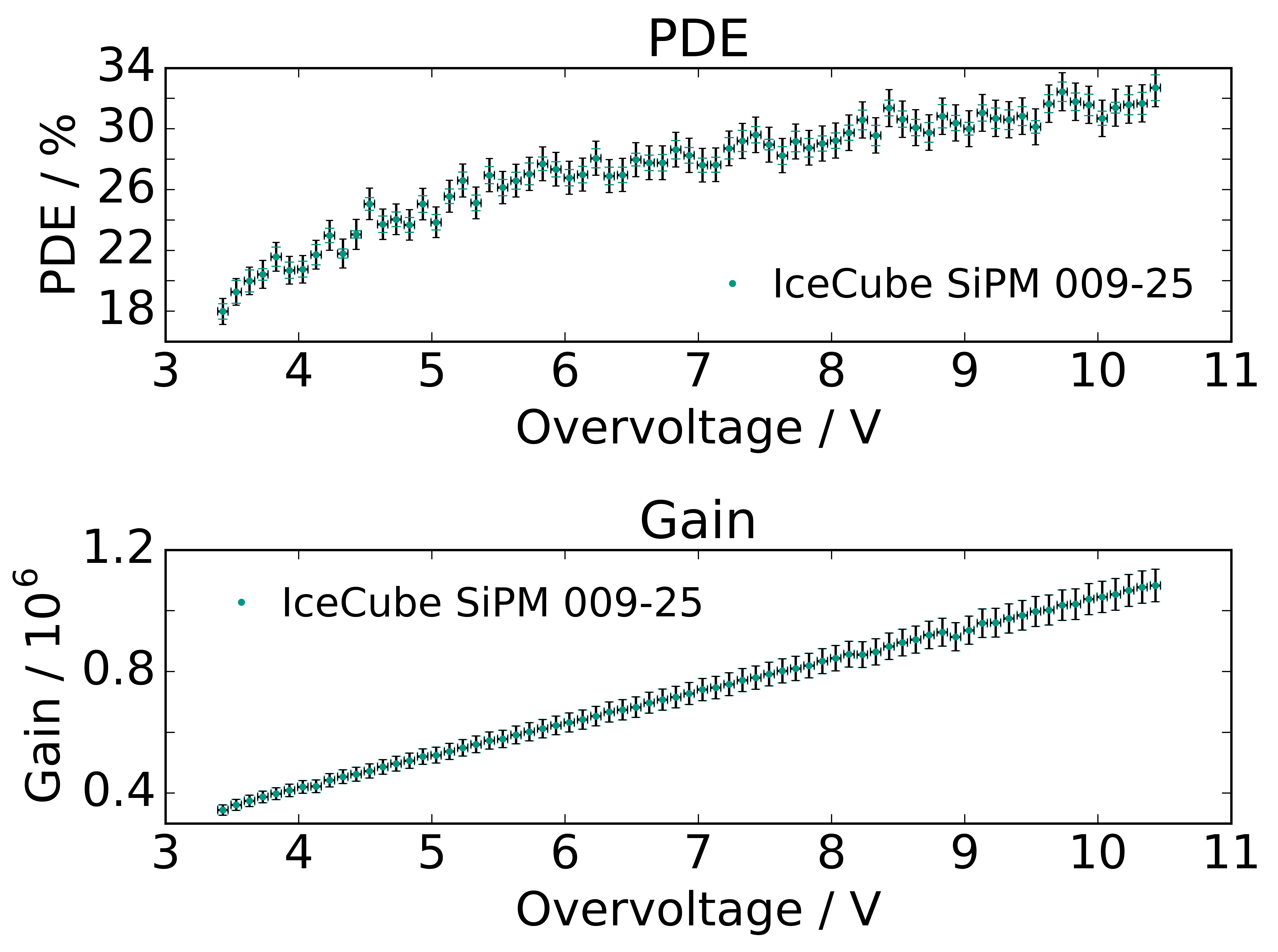
(from M. Oehler)
(Credit: M. Oehler)
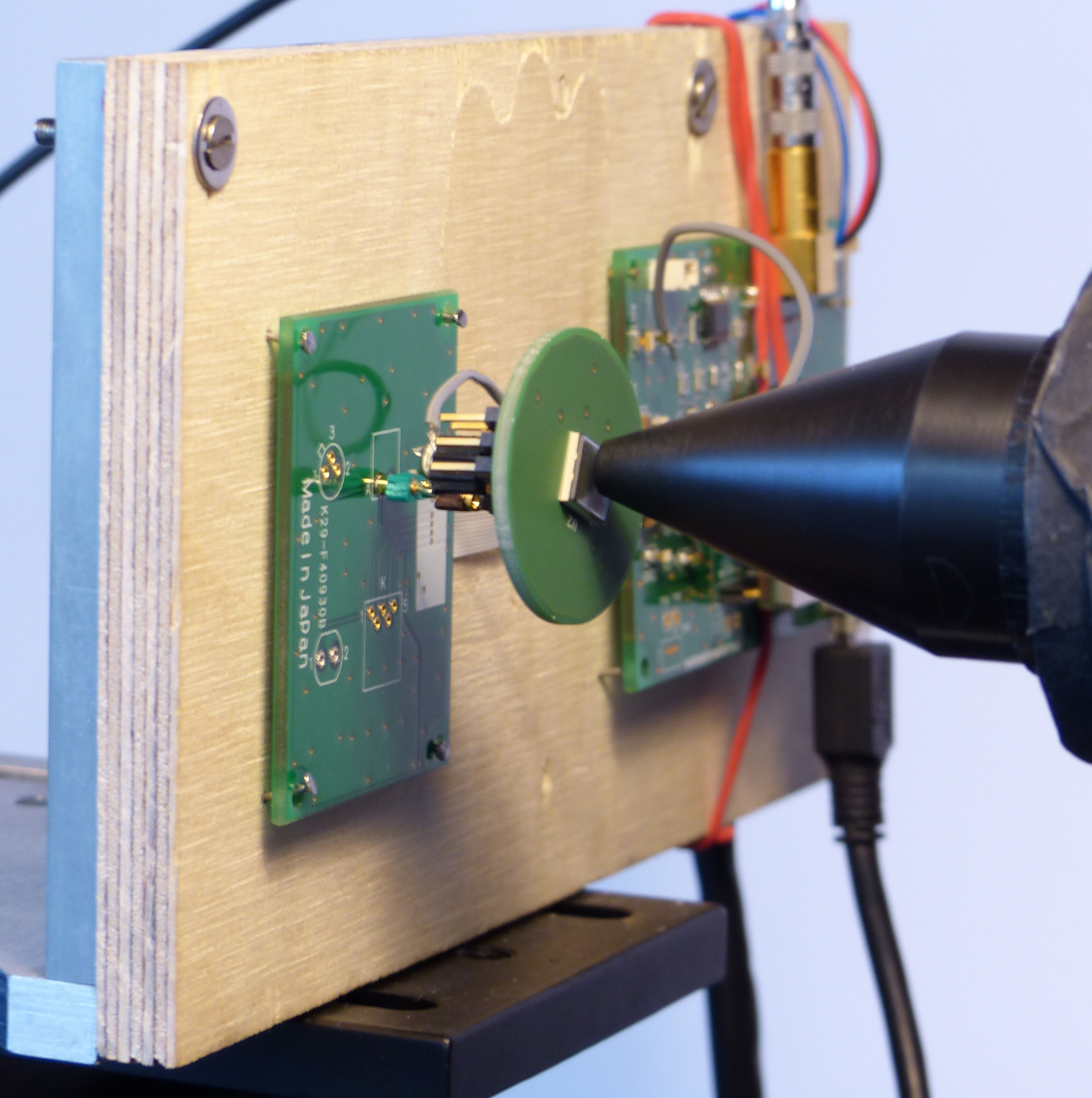
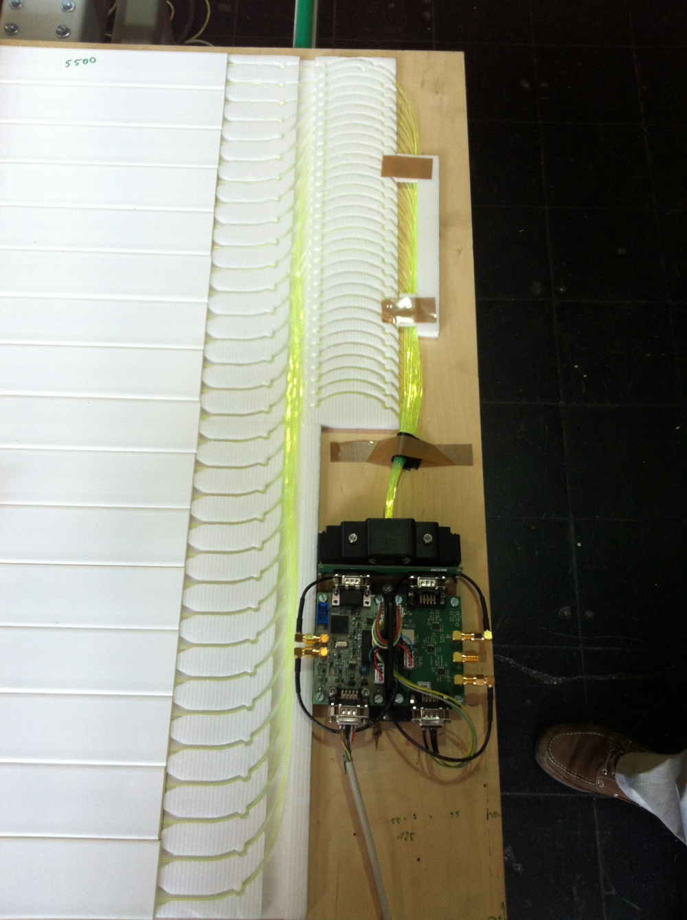
For a first prototype detector several parts of the detector had to be developed, measured and tested for functionality in environmental conditions like at the South Pole. As example, a new analog readout module, consisting of three printed circuit boards, a new optical coupling and a modified routing of the optical fibers was developed. The performance of all prototype detectors was measured with an established calibration setup, the muon tower at KIT.
(Credits: B. Hoffmann)
(Credits: B. Hoffmann)
(Credits: B. Hoffmann)
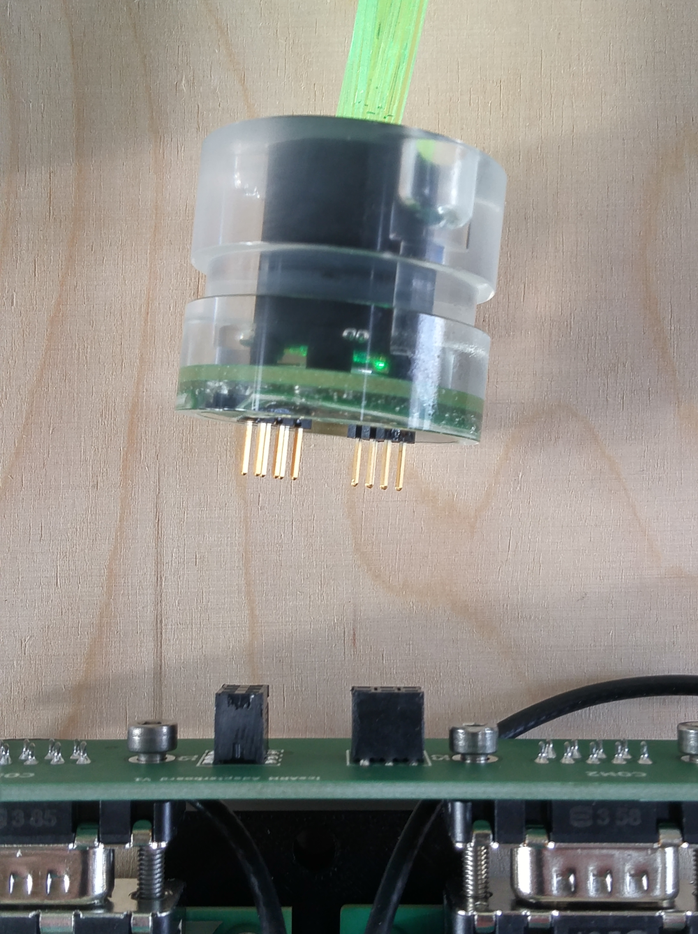
In close cooperation between KIT and DESY the interface between the analog readout and the TAXI DAQ was developed. The SiPM is first connected to an analog readout module that comprises: a cookie board with analog temperature sensor that houses the SMD-soldered SiPM; an adapter board designed for mechanical stability that allows the SiPM on the cookie board to be attached to the ends of the optical fibers coming out of the scintillator bars; a readout board that houses the SiPM power supply (Hamamatsu C11204-02) and three different pre-amplifiers (1x, 5x, 10x); and finally, a general purpose board that contains line drivers to transmit the analog signal from the scintillator panel to the Scintillator Field Hub (SFH) subsystem that includes data handling, power, and timing distribution between the IceCube Laboratory and each scintillator station. The IceTAXI DAQ is an FPGA plus ARM embedded Linux system.
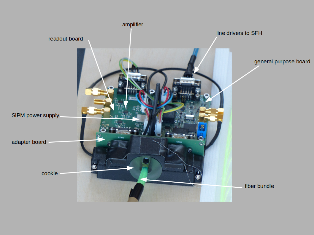
Layout of the analog readout module
(Credit: M. Oehler)
In the season 2017/18 one of these prototype stations was deployed at the South Pole by people from KIT, UW-Madison and DESY.
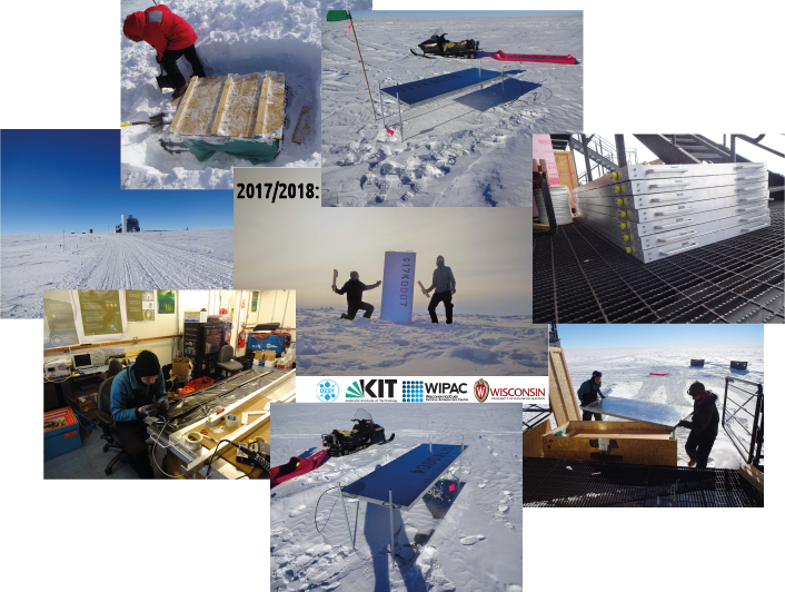
Impressions of detector deployment at the South Pole
(Credits: T. Huber)
The station comprises of seven scintillation detectors communicating with the SFH, where the TAXI DAQ is located. The alignment of the station is an array in hexagonal shape and approx. 60m side length, with the field hub in the middle. In January 2018 the station was deployed and first measurements were done that are very promising.
The next steps are to calibrate the detector station, creating an analysis framework, establishing a data stream with higher bandwidth and analyse the measured air shower events of the station showcasing technological advances for the next generation in cosmic-ray detection.
Further information Part I:
- Paper on The IceTop Scintillator Upgrade
- Paper with SPOCK description:
Part II
Optical Sensors for the IceCube Upgrade
The IceCube Upgrade
The IceCube upgrade is an extension to the existing IceCube Neutrino Observatory at the South Pole. Seven strings of optical sensors and calibration devices will be deployed in a dense configuration in the center of IceCube, like shown below:
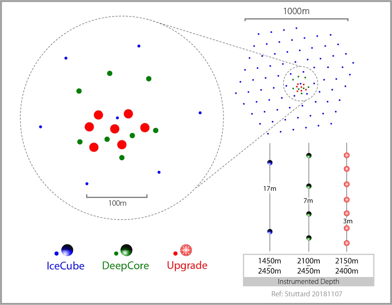
(Credits: IceCube-Gen2)
On the one hand this reduces IceCube’s energy threshold to about 5 GeV, allowing precision measurements of neutrino oscillation parameters, especially tau-neutrino appearance and a test of the unitarity of the PMNS matrix. On the other hand the new calibration devices will enable a much improved in-situ characterization of the optical properties of the glacial ice, reducing one of the largest systematic uncertainties in high-energy neutrino analyses and allowing us to recalibrate ten years of existing IceCube data. Further, the IceCube Upgrade will serve as a R&D platform for optical sensors and calibration devices for IceCube-Gen2. The IceCube Upgrade project started on October 1st, 2018. Deployment is foreseen in the Austral summer 2022/23.
Optical Sensor Development
Several types of optical sensors (Digital Optical Modules (DOMs)) are developed for the IceCube Upgrade project. Low-energy neutrino events typically produce only very little light in the detector, requiring the sensors to be able to detect single photons with a large collection area and a low noise rate. Thus, all optical sensors are based on photomultiplier tubes (PMTs). High solid angle coverage enhances the rejection of atmospheric muon background and a segmentation of the photocathode area can constrain photon arrival direction, improving event reconstruction.
Improved IceCube DOM (PDOM)
 The PDOM is an enhanced version of the IceCube DOM. Qualifying components for suitability to be deployed and frozen in down to 2500 m deep ice is notoriously hard. The PDOM seeks to keep all the well-proven mechanical components (10-inch HQE PMT, optical gel, glass pressure vessel, cable penetrator, harness) of the IceCube DOM. The complex readout electronics of the IceCube DOM is largely replaced by a 14-bit ADC which is continuously sampling at 250 MSPS, allowing triggering and capturing of arbitrary-length waveforms in firmware.
(Picture credits: WIPAC / P. Sandstrom)
D-Egg
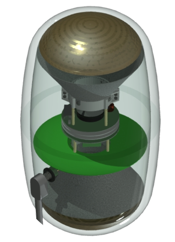
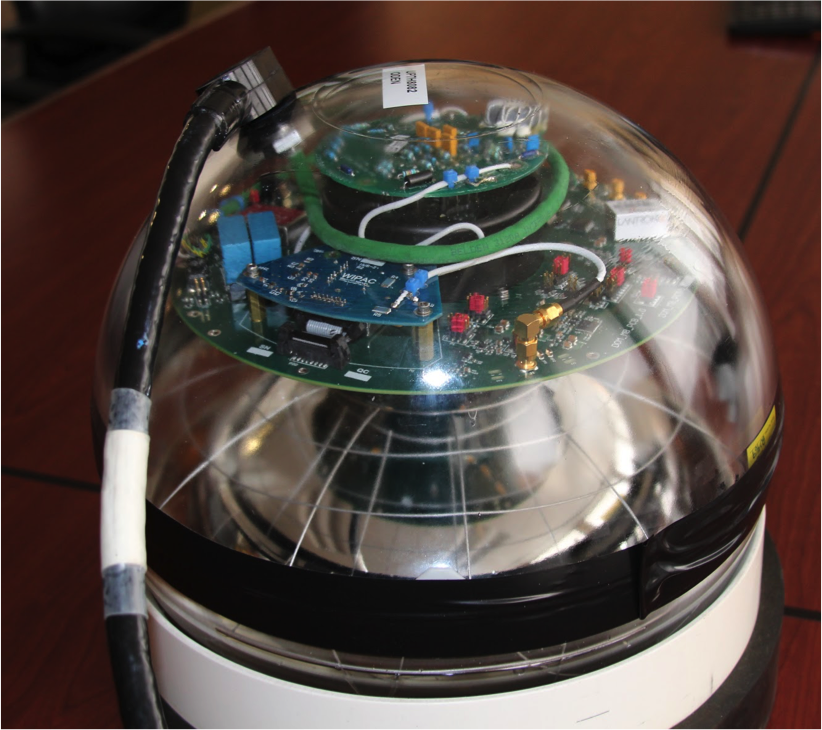
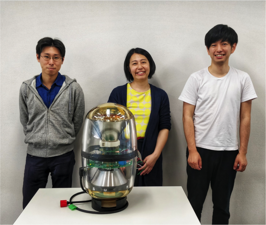 The “Dual optical sensor in an Ellipsoid Glass for Gen2” (D-Egg) uses two 8-inch PMTs looking upward and downward, increasing the effective area compared to the PDOM by about 50% and improving background rejection with the upward-looking PMT. The special design of the glass pressure vessel allows for low material thickness in the region of the photocathodes, increasing the light collection. Reduced potassium content in the glass production reduces background light from radioactive decays in the glass. The elongated shape of the module with a smaller diameter compared to other DOMs will allow in the future to reduce the diameter of the holes drilled in the ice, thus reducing deployment cost and time. The D-Egg readout electronics is adapted from the PDOM by adding a second ADC.
(Picture credits: ICEHAP, Chiba U. / A. Ishihara)
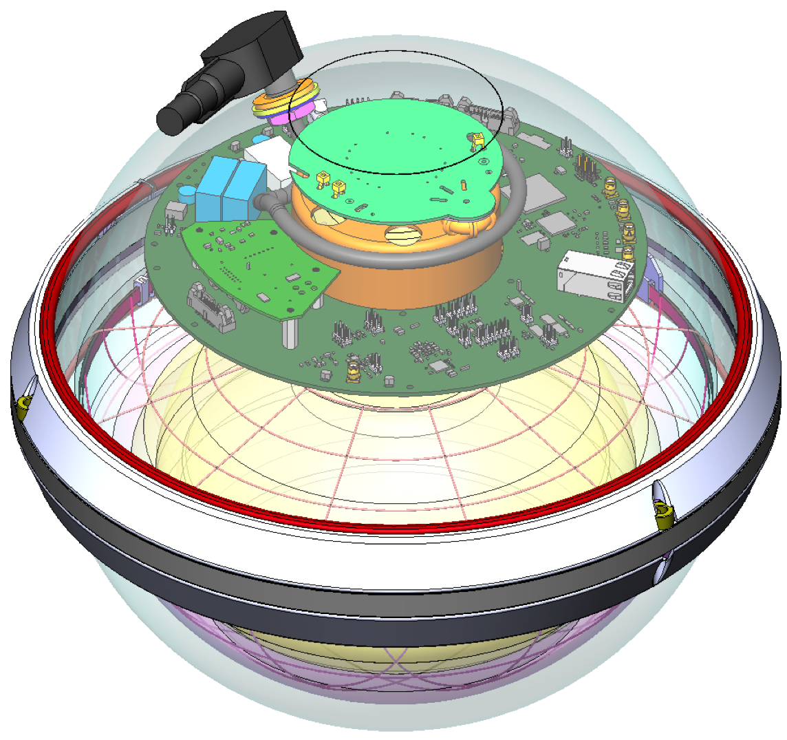
multi-PMT DOM (mDOM)
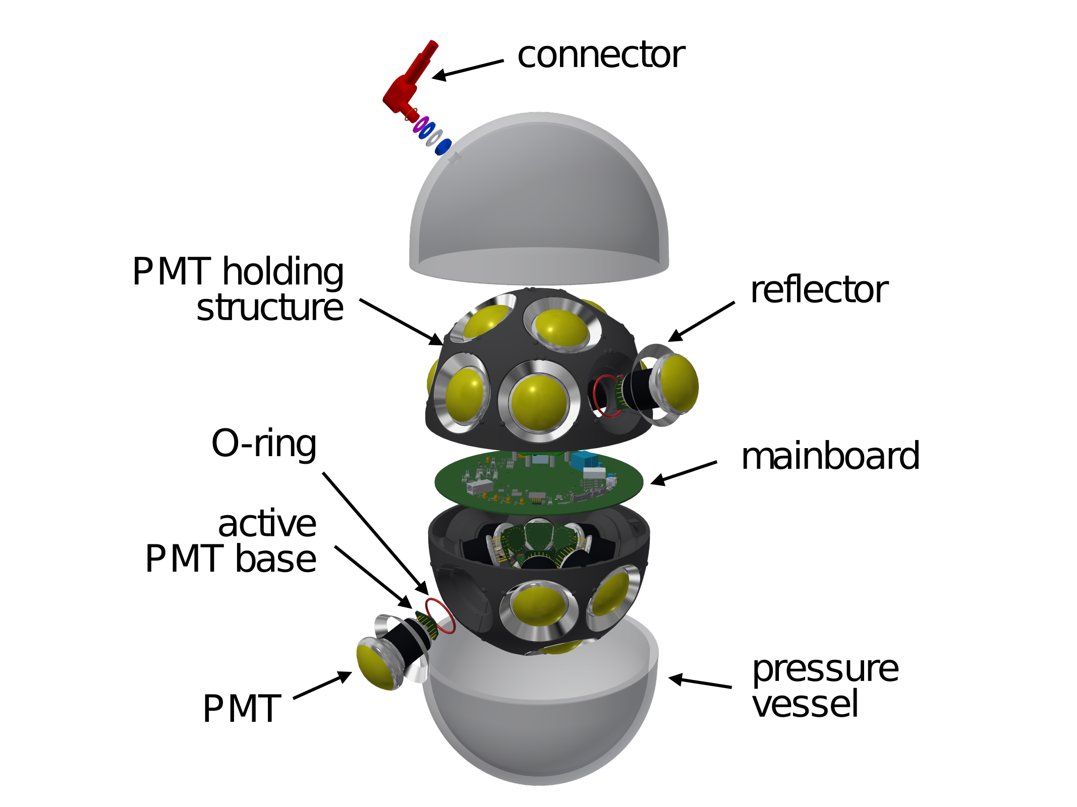
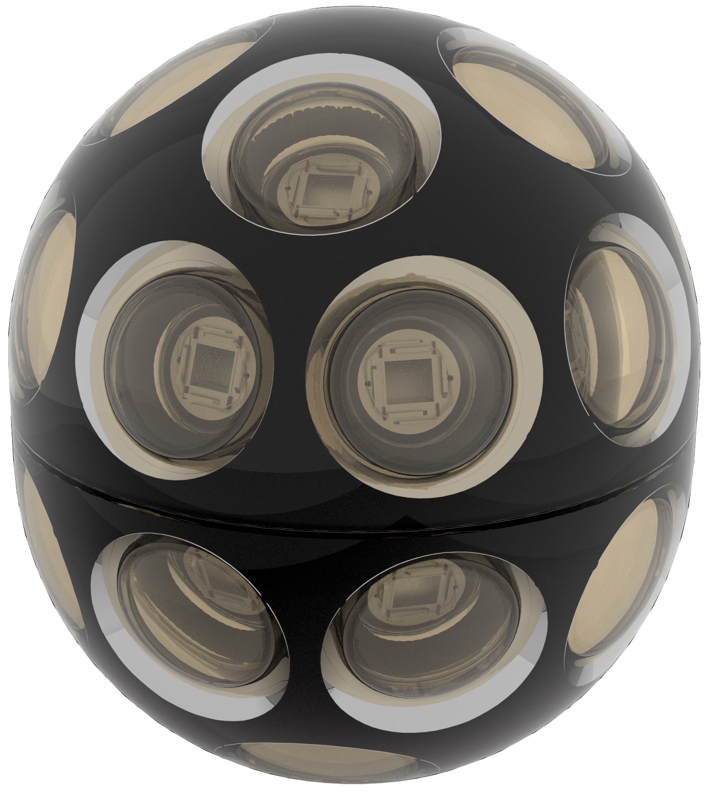 The multi-PMT DOM (mDOM) is adapted from the optical module of the KM3NeT project. The mDOM houses 24 PMTs with a diameter of about 3 inch in a 14-inch glass pressure vessel. The advantages of this design are a large total photocathode area (about 2.2 times the effective area of a PDOM) with directional resolution, improved photon counting, and an almost isotropic sensitivity. Each PMT is read out individually. To reduce the power consumption of the module each channel has a sampling rate of 100 MSPS. The output of a threshold discriminator is used to timestamp the leading-edge time of each signal with nanosecond precision in a FPGA.
(Picture credits: U Münster)
R&D Sensors
A R&D program is underway to develop new types of optical sensors using wavelength-shifting and light-guiding techniques. One example is the Wavelength-shifting Optical Module (WOM). It utilizes a wavelength shifter-coated transparent tube inside a quartz pressure housing to detect the UV part of the Cherenkov spectrum. The incident light is shifted from the UV to the blue. A large fraction of the shifted photons are trapped in the transparent tube under total internal reflection and are guided towards small PMTs at the ends of the tube. These concepts allow for large, scalable, light-sensitive areas with very low dark noise from the small-diameter PMTs needed for readout.
Further information Part II:
- ICRC proceedings on the PDOM
- ICRC proceedings on the D-Egg
- ICRC proceedings on the mDOM
- ICRC proceedings on the WOM
- ICRC proceedings on the POCAM
- IceCube Upgrade project