![]()
In this article we want to give an overview about the GERDA experiment and then present in more detail the liquid argon veto system in the scope of photosensor developments. We give special emphasis on the SiPM-Fiber-System produced at Technische Universität München.
The GERmanium Detector Array, GERDA, aims to measure the neutrinoless double beta (0νββ) decay. A very good background reduction and understanding is essential due to the extremely low rate of double beta decays. To reduce the background from cosmic rays the GERDA experiment is located below a rock overburden of about 3500m water equivalent in the Gran Sasso National Institute (LNGS) of the Italian National Institute for Nuclear Physics (INFN). The detector is located within a cryostat filled with liquid argon which is used for cooling and acts as a distinguished veto system.
The GERDA collaboration investigates the double beta decay processes in the germanium isotope 76Ge, which is a favoured material since normal beta decay is forbidden but the simultaneous conversion of two neutrons with the emission of two neutrinos is possible. The discovery of the 0νββ decay would help to answer fundamental question like the one on the absolute neutrino mass scale. The 0νββ decay also violates lepton number conservation which would establish the Majorana character of neutrinos, which means they are their own anti-particles. The experimental observation of such a decay would shed light on the mechanism generating the present matter dominance of the Universe.
By now no signal was found for the 0νββ decay so the GERDA experiment set a new 90% CL limit of the half life of 76Ge of T0ν1/2 > 0.9x1026 yr and the median sensitivity corresponds to > 1.1x1026 yr.
GERDA Detector
After successful measurements with the GERDA Phase I detector the total mass of the Ge detector array was increased and the veto system was improved for the current Phase II measurements. The Ge detector array of Phase II consists of 40 detectors of which 37 (total mass 35.6 kg) are produced from germanium material enriched by ~87% in the isotope 76Ge and 3 detectors with natural isotopic composition: For Phase I seven enriched coaxial detectors from the former Heidelberg-Moscow and IGEX experiments were installed as well as three with natural isotopic abundance and for Phase II 30 Broad Energy Germanium (BEGe) enriched detectors were added. These germanium crystals act both, as source and detector. Since the rate is still extremely low the background needs to be minimized. Therefore the detectors are arranged in strings within a cryostat filled with liquid argon. This part of the detector is explained in more detail later in this article.

Layout of GERDA Phase II from [1])
(Credit: GERDA collaboration, license CC BY 4.0)
As visible in the above layout, the cryostat itself is surrounded by a huge tank, with 10m diameter filled with ultra-pure water. This acts as passive shield and as medium for a Cherenkov veto system with 66 PMTs. With this system a background index of <10-3 cts/(kev kg year) has been achieved. The detector is completed with a clean room on top of the cryostat and water tank houses which contains a glove box and the lock for assembly and deployment of the Ge detectors.
LAr veto system for Phase II
While the 0νββ-events are confined to the Ge-detector, the background events mostly deposit energy in the surrounding of the detector and therefore produce scintillation light in the LAr peaking at wavelength of 128 nm. The liquid argon veto system is devised to reject mainly γ-ray background from Ra and Th decays in the materials close by to the germanium crystals. It consists of two readout parts, one deployed with PMTs and the other one with wavelength shifting (WLS) fibers and SiPMs. The geometry is defined by the lock system to a lengthy cylinder. The detailed layout of the veto system is shown below:

Layout of LAr veto system from [1]
(Credit: GERDA collaboration, license CC BY 4.0)
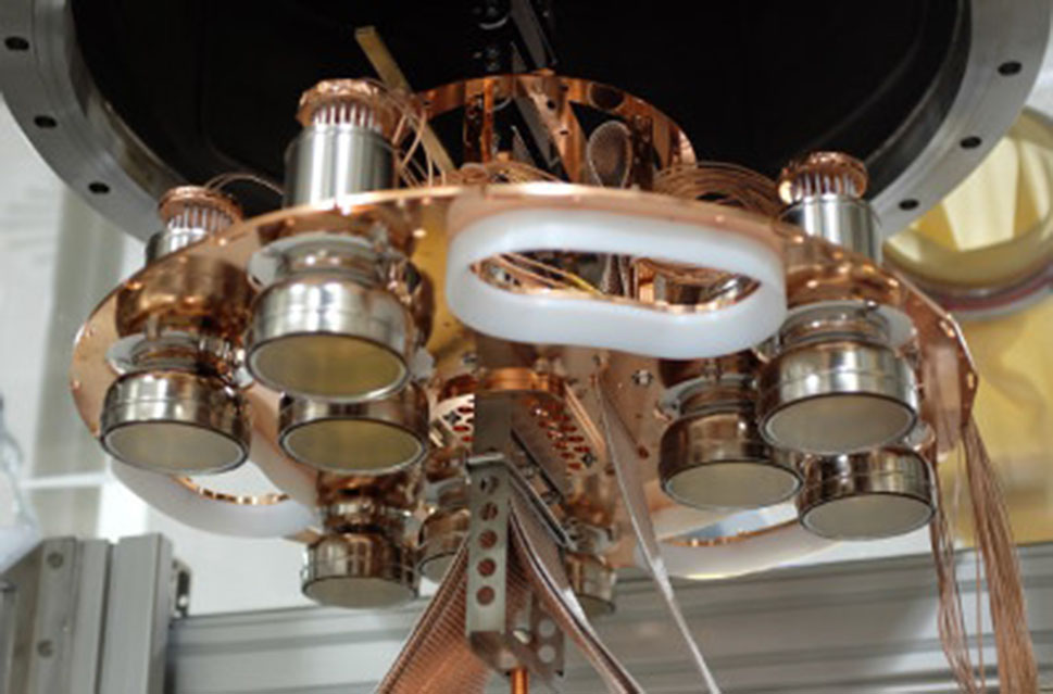
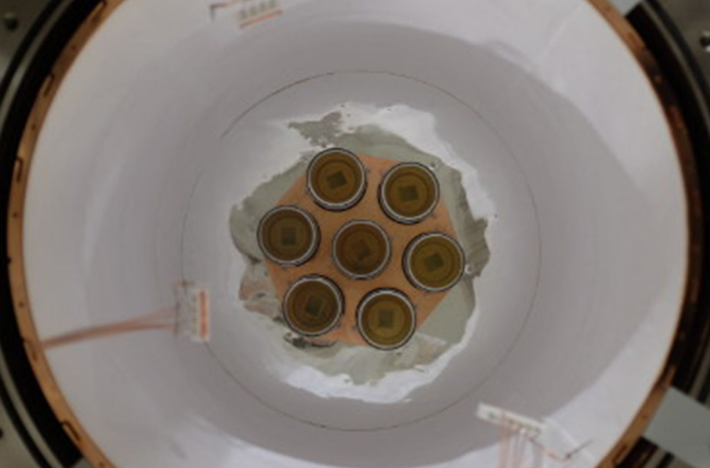
PMT-System
A total of 16 Hamamatsu 3” PMTs are deployed facing from the top and the bottom inwards the cylindrical LAr volume. Copper shrouds separate the copper plates deployed with the PMTs from the central fiber section (see layout of LAr veto system). The shrouds are lined with Tetratex® PTFE foil impregnated with TPB. Thereby it serves as a WLS (from 128nm to 450nm) and diffuse reflector of the shifted light.
(Credit: GERDA collaboration, license CC BY 4.0)
In preceding tests it turned out that the first series of the Hamamatsu R11065 are unstable under cryogenic conditions. The now used Hamamatsu R11065-20 Mod PMTs were developed in cooperation with the manufacturer and were all tested in the LAr test stand LArGe [2] to proof their stability.
These PMTs reach a quantum efficiency of about 40% at 420nm. The bialkali photocathodes are coated with a layer of WLS to allow direct detection of scintillation.
Fiber-SiPM-System
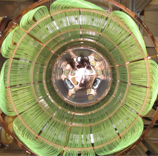
The group of TU Munich developed a novel low-background liquid argon readout sytem based on wavelength shifting fibers which are read out by SiPM arrays. 405 BCF-91A multiclad fibers from Saint-Gobain, coupled on both ends to a total of 90 SiPMs, surround the middle section of the LAr veto system. The squared 1x1mm² fibers are arranged such that their diagonal i.e. their maximize surface is turned towards the enclosed volume.

Fiber curtain with 405 fibers read out on both ends by 90 SiPMs
(Credit: Stefan Schönert, GERDA collaboration)
As can be seen in the above picture the fibers are bundled in units each consisting of 54 fibers that are connected to 6 SiPMs. The design was optimized for large coverage with minimum amount of material to minimize radioactivity.

Custom packaging of three 3x3 mm² SiPMs on a Cuflon® holder, from [1]
(Credit: GERDA collaboration, license CC BY 4.0)
Improving the radio-purity of the liquid argon veto system was the key design criteria. The main issue is the substrate of commercial SiPMs which is mostly made of ceramic or glass fiber PCB material with high radioactivity while the purity of the silicon wafer chips is very high. Therefore it was decided to use commercial SiPMs from Ketek in die and to use custom-built packaging. The SiPMs are placed on a holder made of Cuflon® PCB and bonded to copper stripes. Then the holder is covered with a thin layer of transparent epoxy glue. Two holders build one unit and the 6 SiPMs are connected in parallel to one 50Ω cable. To avoid any electronic component inside the LAr these cables are routed to the lock system and only there, after 20m cabling, the amplifier is connected. Below you find a sketch of the readout system.

Circuit diagram of the SiPM readout, from [1]
Only one channel is shown with six SiPMs in parallel which corresponds to an array of 54 mm²,
the cable separating the SiPMs and the amplifier is about 20 m long.
(Credit: GERDA collaboration, license CC BY 4.0)
So far the SiPMs are working stable in LAr with a trigger threshold below 1 p.e. on all channels. A good SiPM channel has ~200 Hz rate with a dark rate below 20 Hz from 54 mm² SiPM.
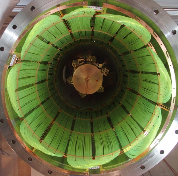
Upgrade of Fiber Module
This first setup of the Fiber-SiPM-system was optimized for low weight with 50% geometric coverage. An improved design is now optimized for coverage leading to 2x higher light yield. A comparison of both fiber curtains are shown below.
(Credit: József Janicskó, GERDA collaboration)
For this new setup more SiPMs are needed and a new packaging was developed at TUM. Instead of 3 SiPMs per holder now 9 SiPMs are placed on each holder and are connected in parallel. The holder is made of quartz substrate with sputtered Al traces and no epoxy glue is on the chips anymore.
Below several pictures from the production are shown:

Machining of fused synthetic quartz (suprasil) with μm precision,
SiPM mounting and bonding, Surface cleaning with Ar-Plasma,
Sputtering of Al traces
(Credit: József Janicskó, GERDA collaboration)

Upgraded holder for SiPMs
(Credit: József Janicskó, GERDA collaboration)
The new wave length shifting fiber shroud and SiPM arrays were deployed in GERDA successfully in spring 2018 and all channels are working with similar gain. The low count rate and excellent single photo electron resolution allows to set a veto condition at for signals with charges >0.5 single photo electron while pertaining a signal acceptance for neutrinoless double beta decay signals of >97%.
Parts of this text and pictures are taken from the paper Upgrade for Phase II of the Gerda experiment [1] which is distributed under the terms of the Creative Commons Attribution 4.0 International License (http://creativecommons.org/licenses/by/4.0/) and from the GERDA website https://www.mpi-hd.mpg.de/gerda/.
Further information:
- [1] Upgrade for Phase II of the Gerda experiment, GERDA Collaboration, Agostini, M., Bakalyarov, A.M. et al. Eur. Phys. J. C (2018) 78: 388. https://doi.org/10.1140/epjc/s10052-018-5812-2
- Optical fiber read-out for liquid argon scintillation light, Janicskó Csáthy, J., Bode, T. et al., https://arxiv.org/abs/1606.04254